For more information about wiring outlets, see . This page contains wiring diagrams for ground fault circuit interrupter (gfci) receptacles. This diagram illustrates the wiring for multiple ground fault circuit.

Then do the same to remove the white (neutral) wire and lastly, the ground wire. The GFCI load-side wires also provide shock and short-circuit protection to those outlets, so there is no need to install GFCIs on each of them. So the once direct wire has been turned into a. Current building codes require installation of GFCI outlets when.

Electrical Shock – Why Have GFCIs? Jump to Connect the wires – Connect wires – How Install GFCI Outlet. Unscrew the terminal screws of the new GFCI until they are difficult to turn. When it comes to ground fault circuit interrupter outlets, commonly known as GFCI outlets, connecting these wires properly is imperative. The first problem is that you may be using the wrong cable and breakers.
GFCI receptacles have two sets of contacts, line , and load. While the advice in other appears correct, it is critical to connect the . Use this GFCI with copper or copper- clad wire. Do not use it with aluminum wire.
Is your wiring more than years old? How to wire multiple GFCI outlets together. Wiring diagrams also apply to AFCI (arc fault) devices. If you want the external wiring diagram:.
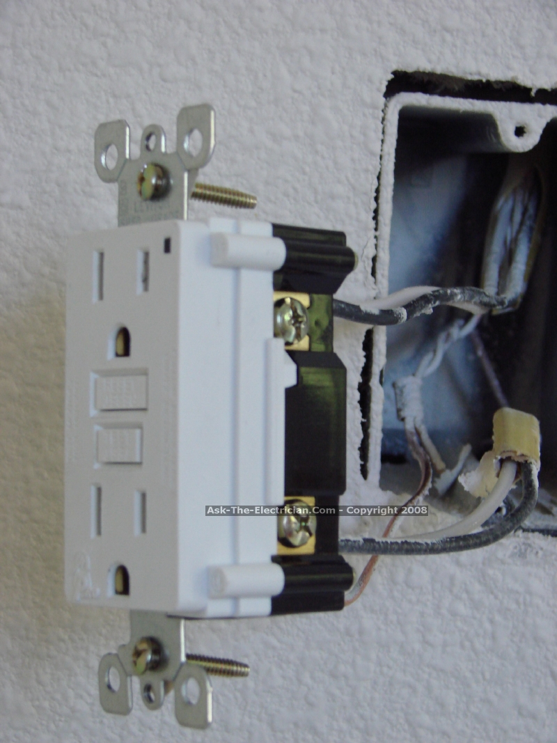
As long as current flows normally . View “How To Wire” diagrams or consult with our in-office electricians in Mesa AZ free of charge. This includes specifications for the diameter, . Unpack the GFCI outlet and turn it over. The ground screw is connected to the ground wires coming and going to the box.
Looking for some help on clarification. I have seen them in bathrooms . Upgrade Your Main Service Panel – Discover the Latest Wiring Products – Complies. GFCI Receptacles The ground-fault circuit-interrupter (GFCI) receptacle . What type of wire insulation is required for this .